Front Wheel Geometry Redesign
In this project, a redesign of the front wheel assembly has been done in order to improve the dynamic behaviour of the car, to reduce weight, to simplify components and to fix errors and problems of the previous design.

Different aspects of the geometry of the wheel interior components, as well as materials and parts have been redesigned and added.
The concept uses the same 10x7'' wheels together with the same 16x7.5-10 tyres. In this manner, the chassis mounting points for the suspension arms can been retained.
Geometry
The most significant change of the new wheel geometry comes in the mounting points of the suspension arms and steering tie rods. These new points define a new geometry of wheel angles and distances. The aim has been to reduce some of the problems of the previous design. Among them was the excessive self aligning torque that translated into the force that the driver had to apply to the steering wheel in order to turn into the corners, especially in low speed corners.
By studying the forces applied from the tyre to the steering wheel, through the tie rod, rack and column, it has been decided to change certain aspects of the geometry of the wheel.
Looking at the assembly from the lateral plane, the caster angle has been changed, which has a direct effect on the mechanical trail, which together with the pneumatic trail, created by the tyre deformation, influences the self aligning torque. The new design leaves a caster angle of 5° which reflects a 12 mm caster trail. The wheel geometry of the previous car was 10.9° and 24.7 mm respectively.
A redesign of the upperlink of the upper arm to the upright and the upright itself has reduced the kingpin angle to 7° from the 9.6° of the previous design, resulting in a scrub radius of 20.9 mm.
The adjustment of these values is of vital importance as they have an effect on the kinematics of the wheel when it is subjected to loads. The new design is a compromise between the feedback the driver has on the front end when driving, together with the resulting loads on the kinematics. It is vitally important that the driver has control at all times, in a comfortable way, of the steering of the wheels. The previous design was designed to present loads of 20 Nm of torque or more on the steering column axis. Exorbitant loads for the rider to handle properly.
Bearings
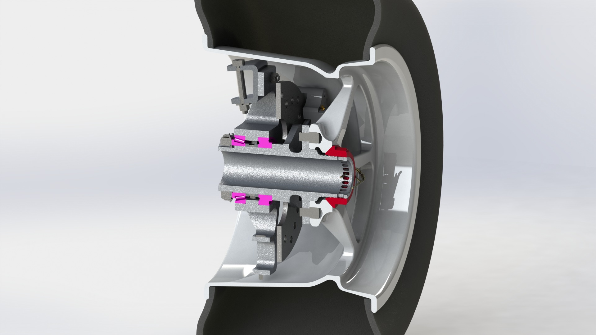
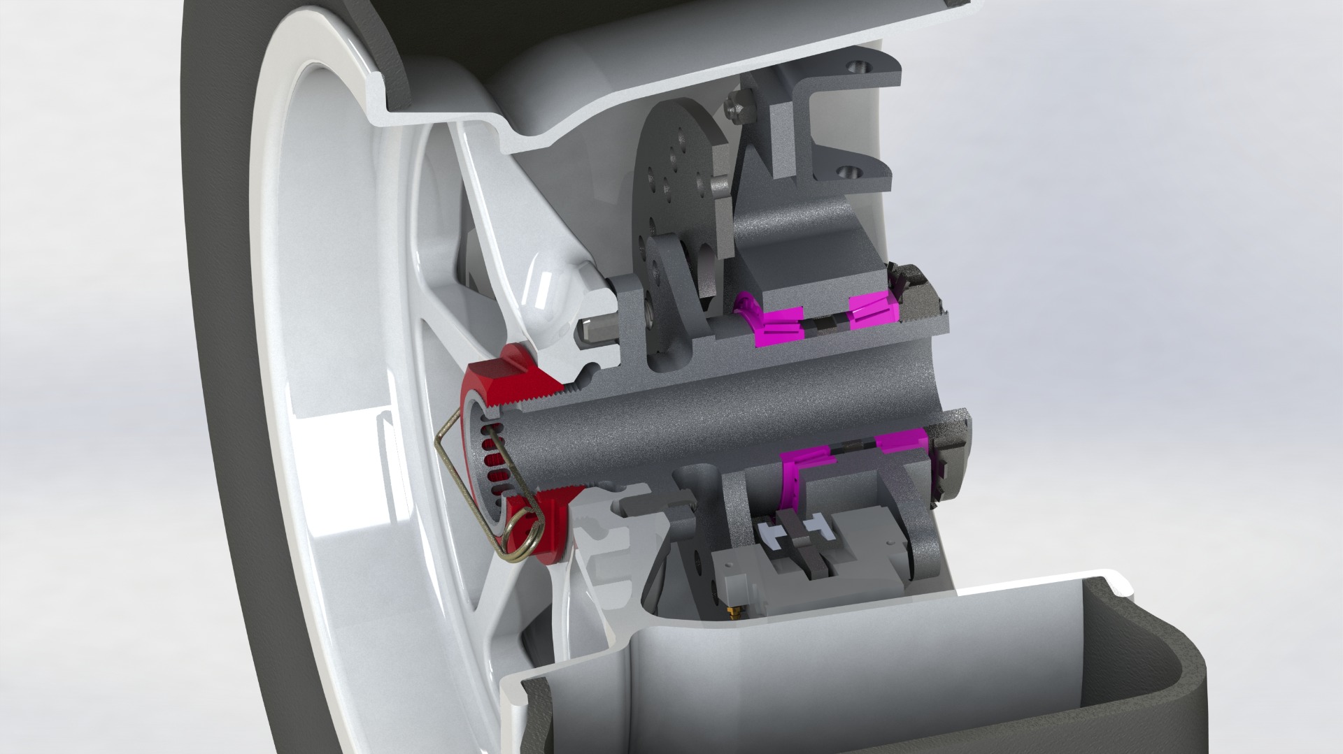
The bearings installed in the assembly are tapered roller bearings, ideal for high radial and axial loads.
With respect to the previous design, the previous bearings have been replaced by bearings of larger diameter and smaller thickness, to adapt to the dimensions of the new phonic wheel that is housed between the two bearings and acts as a spacer between the internal races.
tapered roller bearings are uncommon in these applications. Larger diameter angular contact ball bearings are often used in formula cars for several reasons. They are lighter and are able to support high axial and radial loads. However, they are 4 times more expensive than roller bearings, so more affordable bearings are a better solution.
Toothed reluctor wheel
The previous tone wheel, used for the speed sensor, had the disadvantage that it sometimes collided with the steering tie-rod when it reached its maximum extension. In addition, the mounting of the sensor was affected by the vibrations transmitted by the wheel and the suspension, and this caused errors in the reading.
The new system eliminates these errors. To achieve this it has been necessary to implement a new concept that influences the stub axle and hub designs for a new tone wheel and a new sensor.
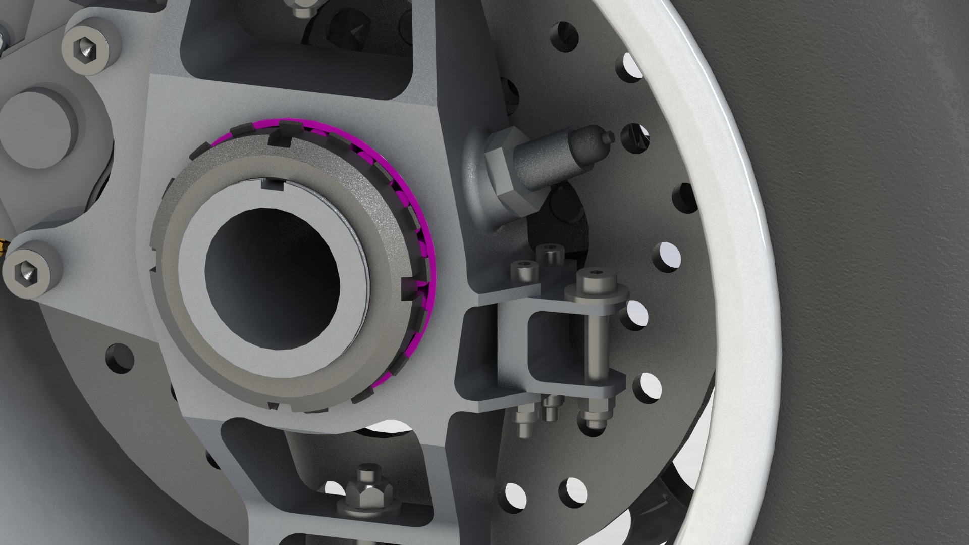
The phonic wheel has been placed in the space between the inner races of the bearings. This also has the function of a spacer between bearings. Bearings and bushings have been adapted and the sensor has been replaced. The new hall effect sensor is bolted to the stub axle. This makes the assembly more compact, and it is also protected against dirt, water and dust.
Steering tie rod mounting
The new design of the steering tie rod attachment allows for a variety of different positions. With this modular solution (a new part bolted to the stub axle) different ackerman geometry configurations can be achieved, as well as changing the distance of the arm between the pivot point and the wheel axle, changing the torque and travel of the arm.
Changing the tie rod mounting point will influence the angle of the tie rod with respect to the steering rack mountings. For this reason, the steering rack mountings must allow displacement in the longitudinal axis of the car.

Uprights and hubs
The uprights and wheelhubs have been redesigned to suit the new modifications. Beyond weight reduction, certain aspects of the geometry have been redesigned according to FEM anlasisys of loads and deformations. Different thicknesses and shapes allow to face the loads in a more efficient way, keeping the same overall weight of the previous parts despite the increase in size.
